MicroMorph3D - a versatile 3D-Scanner
This pages contains a quick start guide to setup and run the MicroMorph3D, a versatile and high-resolution photogrammetric 3D-Scanner.
I run my devises on Windows only, so everything is tested for Windows only.
This page was written pretty quickly on a sunday afternoon, so please excuse a possibly large number of typos ;-)
Built in 2025 for the Ilia State University, Georgia.
Software
Please begin with downloading and installing the latest versions of the following software:to run the scanner software interface,
(optional, but recommended)
to edit the scanned images,
to stack the images from one angular view.
This is still needed (a 30 day test license is available for free), but I'm working on a free workaround. run the 'typical installation' when asked.
to run the 3D mesh creation.
MetaShape is not available as a freeware, but the license is included in the MicroMorph3D package. Reach out to me if you have not received a license from me. There is also a freeawre alternative (Meshroom by AliceVision), which is pretty good but last time I checked (mid-2023), the software was both slower and less accurate compared to MetaShape.
Get the ZIP file from the latest (pre-)release of the MicroMorph3D scanning interface and motor control software from the GitHub page (e.g., MicroMorph3D-0.0.9025.zip).
Un-zip this folder to a place that you can remember and that is accessible in the future, since it contains the software to run the scanner.
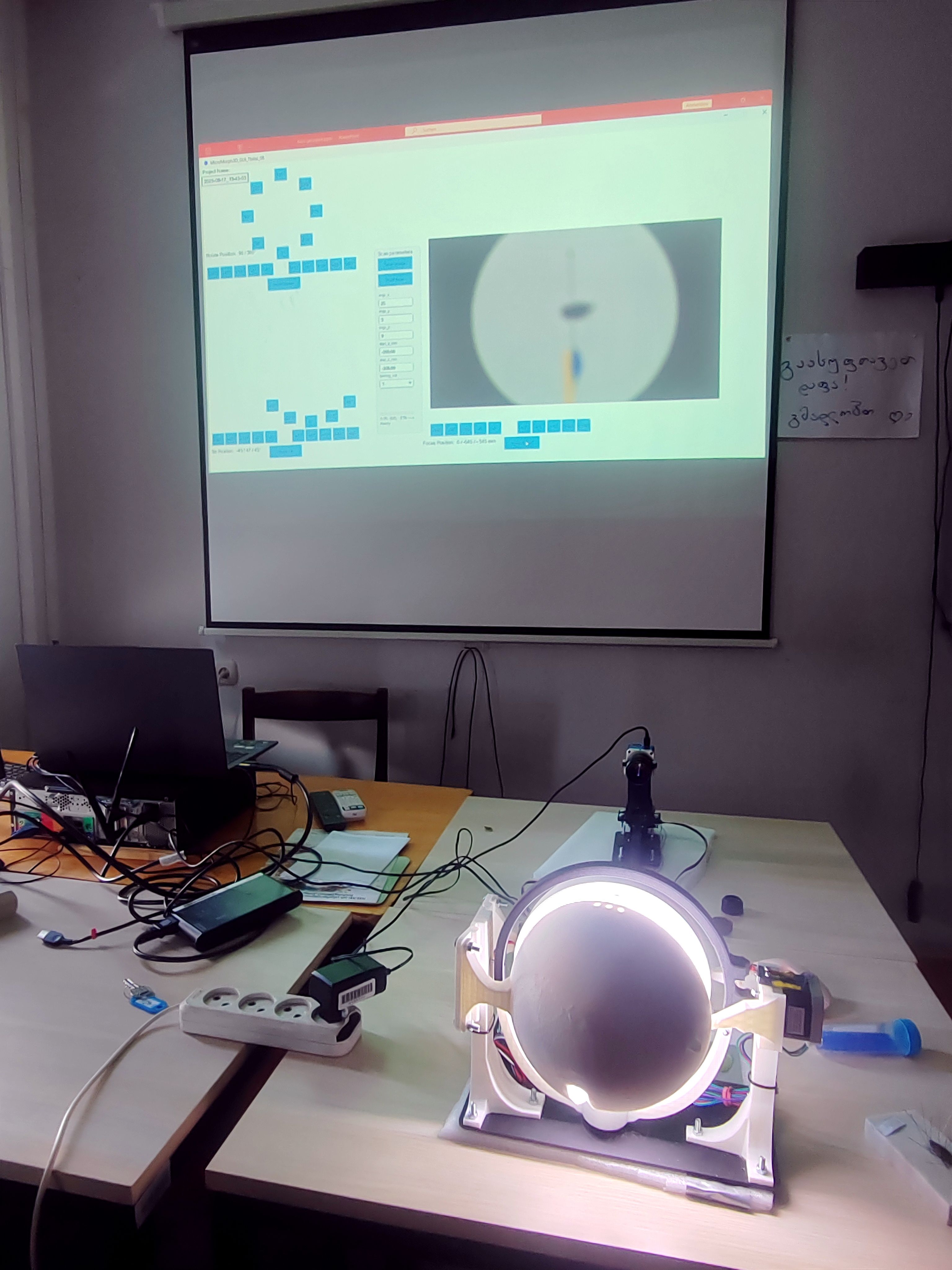
- Start the scanner interface software by double-clicking the processing file MicroMorph3D_GUI.pde (or similar), located in .\MicroMorph3D-x.x.xyz\GUI\MicroMorph3D_GUI\ - the un-zipped folder from above. This will open the source code in the Processing programming environment. Without changing any code, click the "Play" button in the top menu. The scanner software should start with a graphical user interface containing buttons and the camera live view.
- There may be errors like No library found for processing.video: install Video Library for Processing
- To resolve this, go, e.g., to Sktech -> Import Library -> Manage Libraries and search for "Video" to install the missing package(s).
Device setup
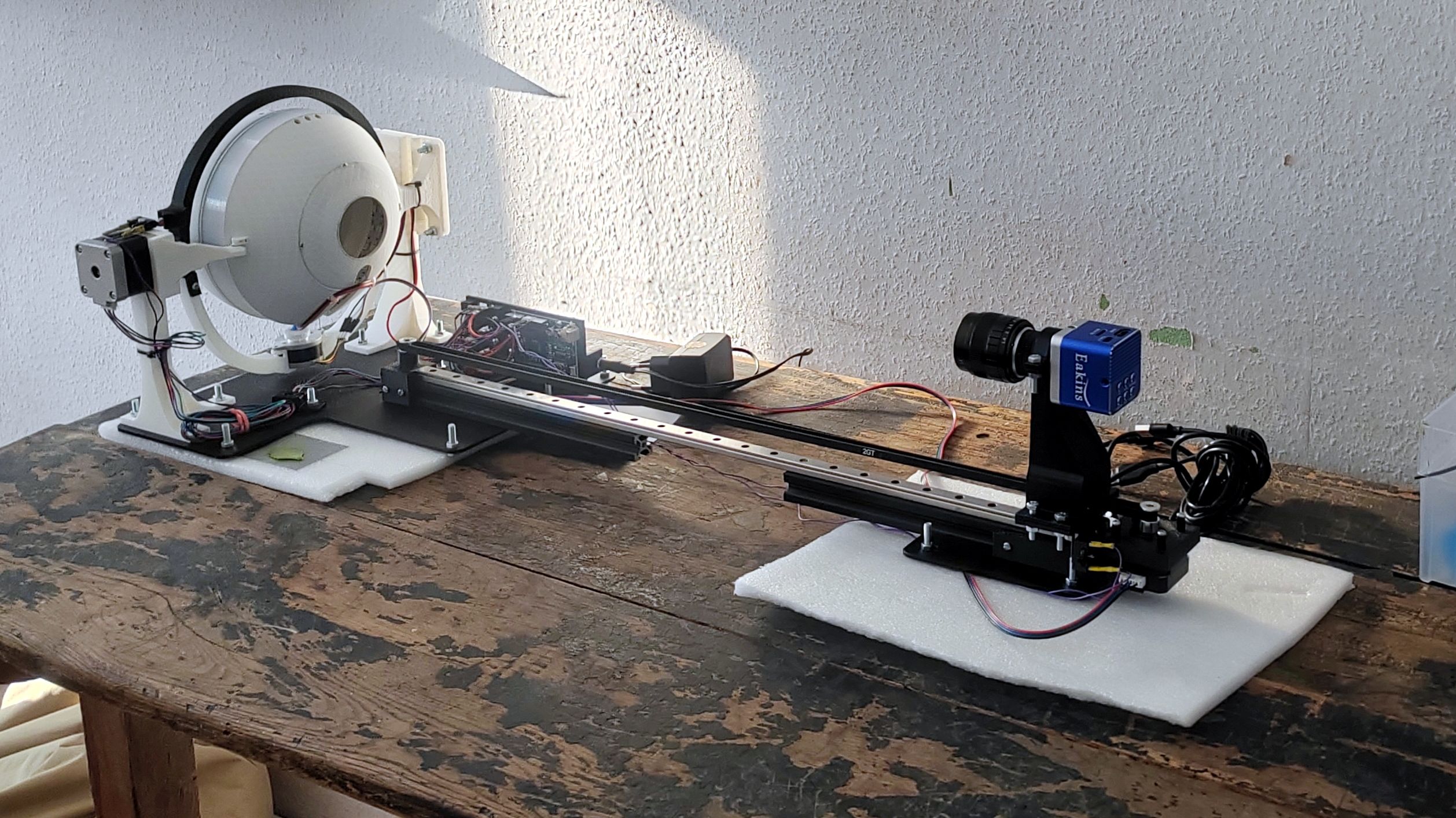
- Insert the micro-USB-cable of the Aduino UNO to your PC.
- Insert the USB-C-cable of the Eakins camera to your PC.
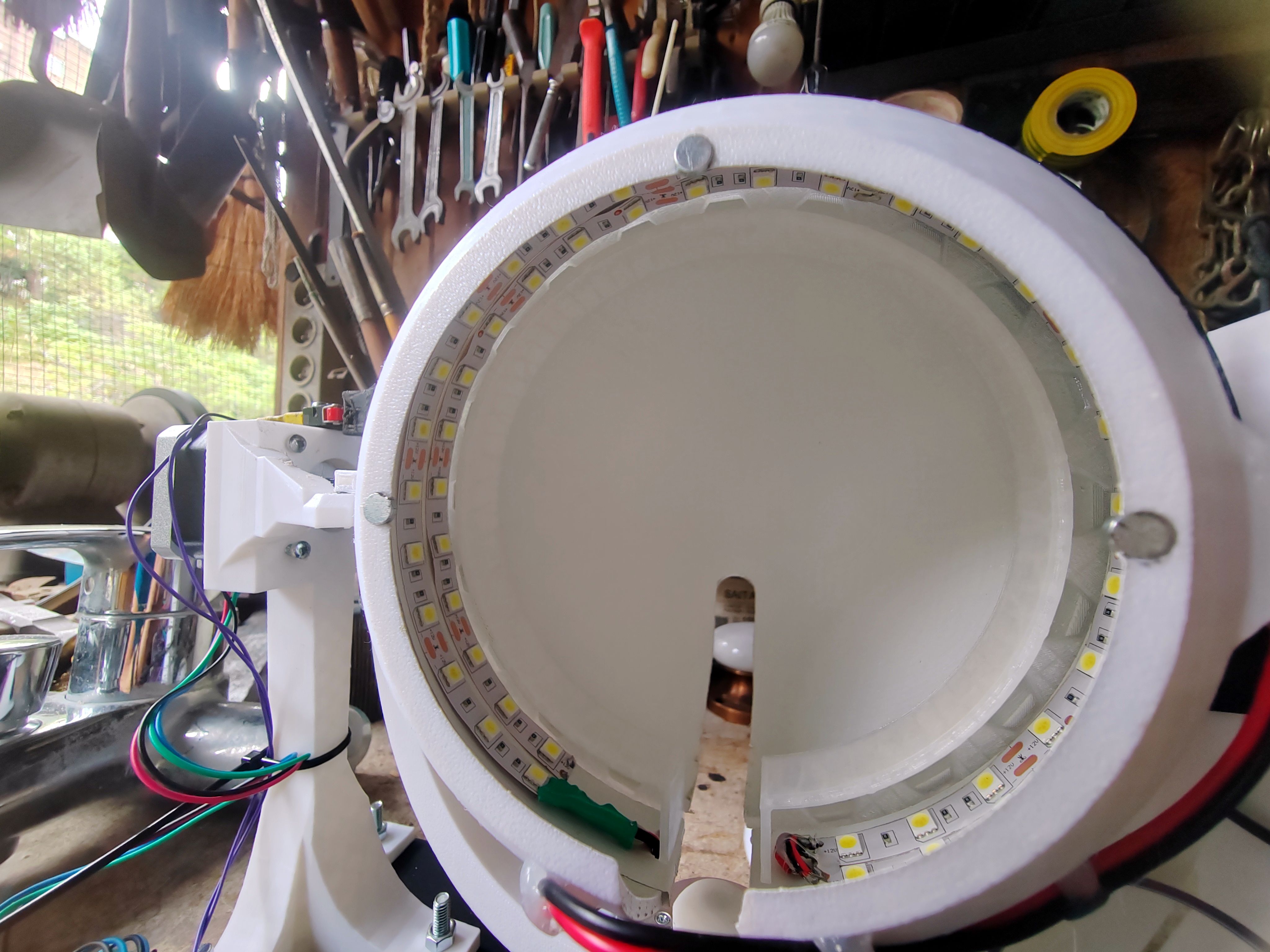
- Insert the 12V DC cable into the round socket at the back of the scanner.
Scanning
Preparations
- If not already done: Start the scanner interface software by double-clicking the processing file
- Click the "Play" button in the top menu. The scanner software should start with a graphical user interface containing buttons and the camera live view.
- Make sure the focus rail (camera rail) is not blocked and click Home Focus
- Make sure the sphere is closed (or fully open) and click Home Tilt
- Make sure that the camera arm is centered so that the camera looks perfectly into the center of the sphere. This is easiest done with without any extension rings between camera and lens.
Centering
- Place a sample on a sample holder
- Put sample holder into scanner and center it as good as possible.
- Use the specimen and arm rotation button of the scanner software to rotate the specimen and see if it really is centered. You may adjust the position of the specimen (right/left), but also the height (up/down).
- I recommend to center the specimen in the rotations 0° and 90°. When the specimen is centered in these two views, it should not rotate out of view in any of the other rotation steps, since, e.g., 180° is the mirrored view of 0°, 270° is the mirrored view of 90°.
- In short:
- Use the software to move camera along the rail so the sample is in focus
- Center sample in 0° rotation
- Rotate sample by 90°
- Center sample in 90° rotation
- Redo centering steps if necessary
Zooming
- Add/remove extension rings to have the specimen as large (format-filling) in the view as possible without it rotating out.
- Set the aperture value of the lens (ranging from 1.4 to 8) to 4. This is where you’ll get the best compromise between sharpness and DOF (Depth Of Field) for scanner work.
- You may also adjust the position of the focal plane of the lens by rotating the frontal lens between the NEAR and FAR settings. (more detailed info on this will follow, but you may play around with the setup to find the settings that best suit your sample)
- A little bit of the specimen may rotate out of view in some of the views (e.g. a long leg or similar), as long as the structure is covered by other views.
- Close the sphere (of not closed already)
- If dislocated, return the ring rotation hinge screw on the right of the sphere back into its hole (this is a design flaw of the current version, I am very sorry about that)
- scanning settings
Scan settings
- Define the scan settings:
- imgs_x: how many rotation steps around the sample should be photographed? (~ 50)
- imgs_y: same as imgs_x, just with ring rotation steps (3-5)
- imgs_z: how many focal planes should be photographed between start_z_mm and end_z_mm? (~12)
- A formula to calculate this will be send in the futur - it is not ready yet.
- The idea is the with every little movement along the camera rail, the focus should shift so that there is an overlap of the two adjacent focal planes of 10-20%. When there is no overalp, the focus-stacking may recover the image with un-focused elements in-between focused elements of the specimen. So rather take a few to many focus steps than too few.
- start_z_mm / end_z_mm: define the positions of the first and the last focal planes
- check the last settings at specimen rotations 90° and 180°, as well as in arm tilt positions (ring rotations) at -45° and +45°, too, to make sure the specimen won't leave the in-focus area at these positions.
Start scan!
- When everything seems fine, start the scan!
Postprocessing
Image cropping and contrast ajustments
- When the scan is finished, drag-and-drop the folder with all images into Fiji (or ImageJ). Uncheck the box "Load as virtual scan". Depending on the number of images taken, this is rather memory-intensive. The purpose is to first reduce the data size by cropping the scan images to only contain specimen data, and then to increase contrast. Both steps are optional but I recommend them. Especially data size reduction will be helpful for focus stacking and 3D-mesh generation.
- Define a rectangle around the specimen. Scroll through the whole stack to make sure the specimen is within this selection box in all slices.
- Press Ctrl+Shift+X or Image -> Crop to crop the stack to the selection.
- Save the new image stack with File -> Save as -> Image Sequence... Create a new folder, e.g. <scan_name>_cr
- Increase the contrast via Process -> Enhance Contrst... with the checkboxes "Process all slices" and "Use stack histogram" checked and "Saturated pixels" at 0.0%. This will strongly increase the cotrast of the images, but may even overdo it a bit. Your choice.
- If satisfied, save the image stack with File -> Save as -> Image Sequence... Create a new folder, e.g. <scan_name>_cr_contr.
Focus stacking
- To prepare the images for focus stacking, the set of images from each angle must be in their own folder.
- Find the script sort-stacks.ps1 in the un-zipped folder MicroMorph3D-0.0.9025\file_sorting\ and move it to the image folder, e.g. <scan_name>_cr_contr/
- Right-click the file and choose "Run with PowerShell". This should sort the images into their new subfolders named by their angular information.
- Open the Zerene Stacker software
- Open the batch mode with Batch -> Open batchmode (or similar)
- Drag-and-drop all just created folders with the sorted images into the batch window
- Check "Save in designated folder (as sourcename_...)" and define a folder, e.g. <scan_name>_cr_contr_stacked/
- Click "Run all batches" and chose PMax with default settings. If you want to try out DMap and other settings, you may play around with this - there are good tutorials for Zerene Stacker in the web.
3D-Mesh generation
- Open the MetaShape software
- I highly recommend getting used to the software but studying the official manual (from Chapter 3. General workflow) and/or browse the web for tutorials and videos. However, if the scan is good and the specimen ot too dark or shiny, the standard and quick worflow may already yield very decent results:
- Drag-and-drop all stacked images into the window
- Workflow -> Align Photos with default settings
- Workflow -> Build Model with default settings
- Workflow -> Build Texture with default settings
- Export -> Export Model and save, e.g. as *.OBJ file
Support